|
|
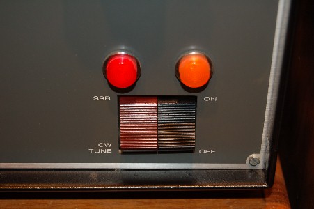
Drake L-4B Amplifier Solid State Relay Modification |
|
|
|
Drake L-4B Amplifier Solid State Relay Modification |
|
|
The Drake L-4B is one of the highest quality amateur amplifiers ever made, a time-tested design, ruggedly constructed, with top notch components. The one weak link in the design is the combined AC power and SSB/CW TUNE rocker switch. This was a custom switch that has been out of production for decades and is today virtually unobtainable, with no available substitutes. The major problem with the AC power switch is that it switches the full 240VAC line. When the amplifier is turned on, the switch is subject to a large surge current while the HV filter capacitors charge up. In addition, when the amplifer is turned off, there is a large voltage transient across the switch, caused by the inductive kick of the plate transformer. (This is a problem also shared by the Collins 30L-1 amplifier, whose front panel rocker switch also carries the full line current. The problem is worse in the Drake amplifer, however, because it runs twice the power of the Collins.) Both of these factors place the switch under considerable stress, and given that replacements are not possible suggest the need for this modification. |
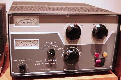
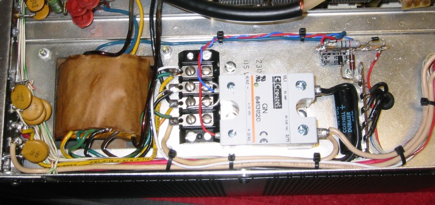
Here is my L4B after this modification and other restorations. In addition to the solid state relay modification, I upgraded the HV power supply filter capacitors and diode string, using an excellent kit available from Harbach Electronics (see the website at www.harbachelectronics.com). The cabinet was refinished by the original paint supplier, Hartzell Manufacturing, in Dayton, Ohio. That and a new pair of 3-500Zs result in an amplifier that not only looks good but should last for another thirty year span. |
|
|
The modification described here takes the load off the AC ON/OFF switch by using a solid state relay to switch the AC 240V line. The switch now only toggles the relay on and off, which requires it to handle a miniscule 10 mA of control current. Another approach to protecting the ON/OFF switch is that employed by the Harbach Electronics "soft start" modification kit, which reduces the starting surge current by inserting a momentary series resistance in the AC line. While this latter approach is certainly helpful, it still requires the power switch to conduct the full AC current of the amplifier, roughly 15-20 amperes under peak load. Note that neither modification protects the SSB/CW TUNE switch. Fortunately, the demands on this switch are lower, and failures are rare. Nevertheless, it is good practice to minimize "hot switching" the SSB/CW TUNE switch in order to preserve its life |
|
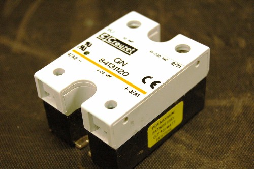
A word about solid state relays: SS relays are SPST devices with four terminals - two for switching the load, and two for control (analogous to the coil on a mechanical relay). There are separate specifications for the control and load. Most SS relays require a control voltage of about 4-30 VDC, although some (usually these are more expensive) require an AC control voltage. Similarly, the relay's load rating will specify either AC or DC voltage, as well as the maximum current and voltage limits. For this modification, you will need an SS relay that uses a DC control voltage in the range of 3-15V (or more), and an AC load rating of at least 240VAC and 25 Amps. Obviously, higher ratings are no problem. (The relay here was rated at 560VAC at 50Amps, because that is what I had in my junk box.) SS relays are common and inexpensive ($20 or less) and are widely available on eBay. I often buy them from Marlin P. Jones Associates (www.mpja.com), a company with great prices that I have used for years and can strongly recommend. Although I used a DC control relay, you could also use an AC control relay and delete a diode and capacitor. However, AC control relays can be pricey, so I'd advise sticking with the DC control ones if you want to hold down the cost. Whichever you use, however, it MUST be rated for an AC load. You can't use a relay for this modification designed to switch a DC load.
|
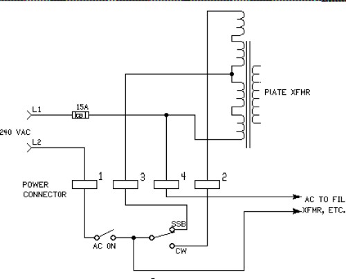
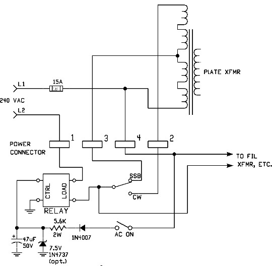
To the right is a simplified schematic diagram of the L4B's original ON/OFF and SSB/CW switch wiring. The "power connector" in the diagram corresponds to terminals on the 8-pin Jones connector on the rear of the L4B RF deck. (The pin numbers are hard to see, but are on the solder lug side of the connector.) Wiring shown below the power connector is in the RF deck, while wiring above the power connector is in the power supply.
Note that the 240V line L2 is routed through the AC ON/OFF switch, which is the problem our modification is intended to fix. The SSB/CW switch routes 240V to different taps on the primary of the plate transformer. |
|
|
|
|
The modified wiring is shown in the simplified schematic diagram on the left. Note that the SSB/CW wiring is unchanged from the above drawing, but that the "Load" side of the solid state relay is now in series with the 240VAC L2 line. In this new configuration, the ON/OFF switch, when closed, connects 120VAC from L1 to the 1N4007 diode. The waveform at the cathode end of the diode is a half-wave rectified AC, with a peak value of about 170V. Most of this voltage is dropped across the 5.6K resistor, and the remainder is filtered by the 47 uF electrolytic capacitor. The current flowing into the relay control terminals is about 10 mA, and the voltage is about 7VDC with one or two volts of ripple. The 7.5V zener diode is not essential, but is intended to clamp the voltage at the relay and provide some protection against voltage spikes on the AC line. I included the zener diode in my design, but builders should feel free to leave it out. Interestingly, the 10 mA current drawn by the solid state relay is independent of the control voltage across its terminals. |
|
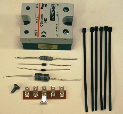
Here are the parts you'll need to make the modification to your L4B: (1) Solid State Relay (DC control, AC load). See above paragraph. In addition, you'll need these tools: a variable speed hand drill with a 1/8 in bit, a screwdriver, a soldering iron, wire cutters and small electronics pliers. |
] Needed parts for the modification. The total cost should be under $20, even if your junk box is depleted.. |
|
 |
STEP-BY-STEP INSTRUCTIONS 1. After removing all cables, turn the L4B RF deck upside down on a soft work surface and remove the bottom cover (6 screws). There is no need to remove the top cover. Face the rear of the RF deck toward you. 2. Note the three 8-32 screws that secure the large ceramic coil form to the chassis. Remove the screw nearest the front of the chassis. (As shown on the left, I countersunk the hole and replaced the screw with a flathead screw. There is no need to do this, however, unless you're compulsive. The coil form is still secured by the two remaining screws and its wiring and isn't going anywhere.) |
|
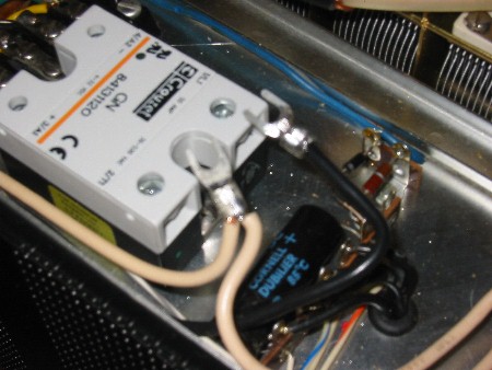
3. Loosen the 8-32 coil form screw on the bottom right in the above photo, slide the slotted flange in the relay under the screw head and temporarily secure the relay to the chassis. The relay body will cover the hole you vacated in the previous step. 4. Using the relay mounting flange as a template, drill a 1/8 in. hole in the chassis, which will be used for mounting the relay. NOTE: drill slowly, using a piece of sticky tape to remove the metal chips. Do NOT use a center punch to mark the hole, since you don't want to shock the fragile 3-500Z tubes! 5. Smear a thin coat of thermal grease on the relay base to ensure good thermal contact with the chassis. (Hint: thermal grease is sold at Office Depot in their computer section.) 6. Now mount the solid state relay to the chassis, using a #8-3/8" sheet metal screw in the hole you just drilled, and also the screw from step 2. Be sure the screws are tight. The LOAD terminals on the relay face the ON/OFF switch. |
 |
|
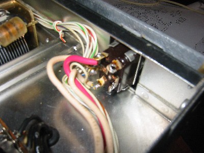
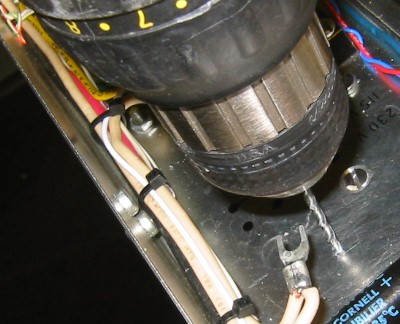
7. Clip and discard all the wire cable ties in the wire bundle that goes from the ON/OFF switch to the 4-terminal barrier strip. (Three of these ties are visible in the above photo.) Later, we will use Ty-Wraps to secure the bundle. 8. Inspect the dual ON/OFF and SSB/CW switch module, and unsolder the heavy black wire from the top terminal on the ON/OFF part of the switch. Next, clip the jumper from the bottom terminal and remove the excess solder from the two terminals. When you're done, the switch should look like that in the below photo. 9. Note the heavy white wire connected to the middle terminal of the SSB/CW switch. Clip the white wire 6.5 inches from the middle terminal.. Strip about 1/4 in. from the clipped ends and insert both ends into the LOAD terminal on the solid state relay that is nearest the side of the chassis. There will be enough slack in the white wire to do this. (Hint:attach a spade lug if desired to the wire ends.) |
Thermal heatsink grease: A little dab'll do you. |
|
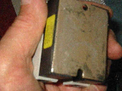
Clean the solder off the two terminals of the ON/OFF switch so you can attach wires to it in a later step. |
You can attach spade lugs to the wires that attach to the solid state relay, if you want an especially professional appearance. |
|
|
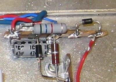
10. Remove 2 inches from the free end of the heavy black wire that you removed from the ON/OFF switch in step 8. Strip 1/4 inch from the end of the wire and insert it into the other LOAD terminal on the relay. You can attach a spade lug to the wire if you prefer, as shown in the above right photo. 11. Note the 2-lug terminal strip shown in the above right photo. Clip all three connections to the terminal strip (blue wire, diode, and 2.2K resistor) as close to the terminal strip as possible, leaving as much lead length as possible on the diode and 2.2K resistor. 12. Remove the 2-lug terminal strip and replace it with a 5-lug terminal strip. Then reconnect the blue wire, diode, and resistor to lugs 2 and 3 on the new terminal strip. (Lug 1 is nearest the rear of the chassis.) Note that the 2.2K resistor goes to the ground lug, as shown on the right. |
|
|
|
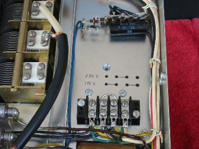
13. Referring to the circuit diagram and the above right hand photo, install the 5.6K resistor, 47 uF electrolytic capacitor, 1N4007 diode, and the (optional) 1N4737 zener diode on the remaining lugs on the new 5-lug terminal strip. Be sure that the "-" lead on the electrolytic capacitor is attached to the ground terminal, and that you observe the correct polarity for the two diodes. 14. Route two lengths of hookup wire from the terminal strip pin 1 (where the positive capacitor lead is attached) and pin 3 (the ground lug) to the two CONTROL input terminals on the solid state relay. The wire from pin 1 on the terminal strip goes to the POSITIVE (+) control terminal on the solid state relay. 15. Route a length of hookup wire from the empty bottom lug on the ON/OFF switch to the 4-terminal screw-type barrier strip. Connect the wire to the barrier strip terminal that has the green wire from the filament transformer connected to it (the terminal nearest the center of the amplifier). 16. Connect a short length of hookup wire from pin 5 of the 5-lug terminal strip (where the anode of the 1N4007 diode is connected) to the empty top lug on the ON/OFF switch. In the above photo, this is the red wire on the right. 17. Dress all the wires neatly together and secure the bundle with Ty-Wraps, as shown below. 18. Before buttoning up the amplifier, check your wiring and make certain there are no metal chips or wire fragments in the chassis. Now reinstall the bottom cover of the RF deck and you are done!
Here is the completed modification. Now when you turn on your L4B and hear the "kerchung" from the power supply (caused by the sudden onset of transformer flux exerting a magnetic force on the power supply's steel enclosure), you can rest easy knowing that none of that surge current is going through the AC ON/OFF switch. A final request: drop me an email when you're done telling me how the modification went and if you found any of these instructions confusing. Thanks and best of luck! -- Jim W8ZR |
||
|
|
|
|